


 EN
 ไทย


Customers Also Purchased


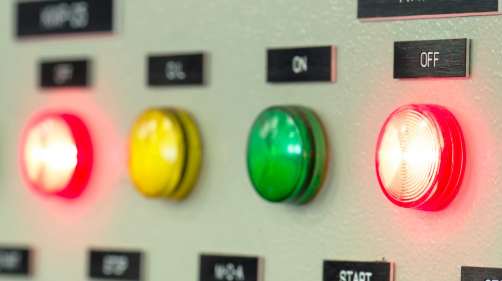
Pilot LightsIn a control panel, its purpose is to help operators see the system status without having to open the enclosure or troubleshoot internal circuits. Some lights indicate that the panel has incoming power, some show that a motor has been commanded to run, while others serve as warnings when an overload trips or a system fault occurs.
When a single panel contains multiple pilot lamps, considerations extend beyond just choosing colors or drilling neatly aligned holes. You must consider what status each lamp is indicating, where its signal originates, what voltage it uses, and whether operators can interpret the displayed light correctly. If circuits are wired improperly, a lamp might stay on even when the machine is not actually operating, turn off while parts of the panel are still energized, or display redundant statuses that cause confusion rather than making system inspection easier.
Start by defining what each light is intended to indicate
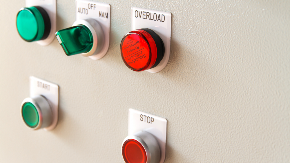
Before selecting colors and mounting locations, the function of each pilot lamp should be clearly defined first. For example, whether it is intended to show that the panel is energized, the system is in automatic mode, the motor has received a run command, or a protective device has tripped the circuit.
These statuses look similar, but in circuit terms, they have different meanings. For example, a light connected downstream of the main breaker may indicate that voltage has entered the panel, but it does not confirm that the control unit is ready to operate. Meanwhile, a light wired in parallel with a contactor coil indicates that voltage is supplied to the coil, but it still cannot verify whether the contactor has pulled in successfully, whether the main contacts are conducting across all phases, or whether the motor is actually rotating.
If you want the lights to display indications straightforwardly, the signal meanings should be categorized into different levels, such as:
- Power On Indicates that voltage is present at the signal tap point
- Run Command Indicates that the system has sent a command for the machine to operate
- Contactor On Indicates that the contactor has responded according to the status of auxiliary contacts
- Running Feedback Displays actual operational feedback from sensors or feedback devices
- Trip or Fault Indicates that protection systems or detection devices have detected an abnormality
Labeling clearly from the start helps reduce problems such as a Run light staying on while the motor is not turning, or a Ready light being misinterpreted as the machine being in a safe condition for maintenance.
Select signal pickup points that match the intended meaning
One common mistake is choosing a connection point simply because it is nearby or convenient for wiring, even though the signal from that point does not genuinely reflect the desired status.
If the goal is to show that the system has sent an operation command to the motor, the signal can be tapped from a PLC output, control relay, or contactor coil circuit. However, that lamp should be labeled consistently with its meaning, such as "Run Command", and should not mislead operators into believing it confirms that the motor is running.
Wiring the lamp through a contactor's auxiliary contact provides feedback that reflects the contactor's response to a command better than wiring in parallel with the coil. However, standard auxiliary contacts do not confirm that all power contacts are operating properly, nor can they verify the condition of the motor or the downstream load.
If you need to know the actual operational outcome, you should use signals from feedback devices appropriate for the system, such as tachometers/speed sensors, pressure switches, flow switches, limit switches, or position sensors. The signal pickup point must therefore be chosen based on what needs to be verified, not selected simply from the easiest wiring location.
Use colors systematically, and do not rely on color alone
Pilot lamp colors help operators distinguish statuses quickly, but they should follow a consistent system across the entire panel or, ideally, across the entire facility so that the same color does not carry conflicting meanings from one machine to another.
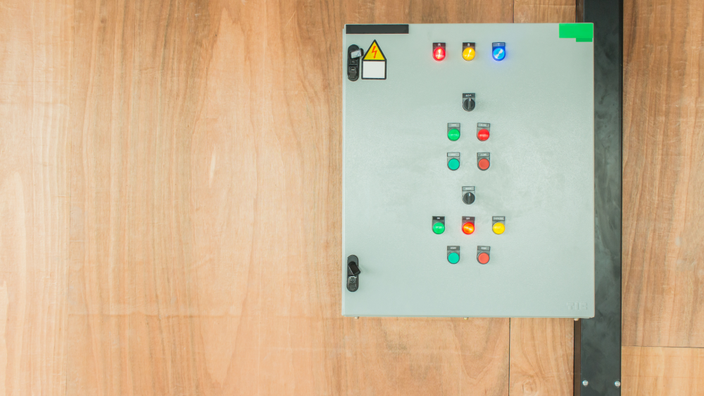
Generally, red is commonly used for abnormal conditions, danger, or situations requiring immediate attention. Yellow or amber is used for warning statuses or conditions that warrant inspection. Green is typically used for normal or safe conditions, while blue may be used for statuses requiring specific operator action. However, specific definitions must adhere to the standards adopted by the project, risk assessments, and the facility's internal regulations.
Meaning should not be defined by color alone, as lighting conditions, dust, oil stains, or lenses faded with age can make distinguishing colors difficult. Some operators may also have difficulty distinguishing certain color pairs. Therefore, labels or symbols should be placed near each lamp, such as POWER, AUTO, MANUAL, MOTOR RUN, OVERLOAD TRIP, or SAFETY CIRCUIT FAULT.
Names on the panel face should match circuit diagrams, machine manuals, and text on HMI screens. If the same status is referred to by multiple names, maintenance personnel will waste time interpreting meanings and are more likely to inspect the wrong area.
Check the voltage of every pilot lamp; do not judge by appearance.
Pilot lamps with identical shapes, colors, and sizes may be designed for different voltages, such as 24 V AC/DC, 110–120 V AC, or 220–240 V AC. This difference often cannot be seen from the front; you must check the device label, model code, or manufacturer documentation.
Many control panels contain more than one voltage level inside, such as 380–400 VAC for power circuits, 220 VAC for some control circuits, and 24 VDC for PLC circuits. Installing the wrong pilot lamp model can result in issues ranging from failure to light and abnormally dim light to damaged LED modules.
When installing multiple units, the voltage should be clearly indicated in the circuit diagram, equipment list, and panel interior labels. Do not rely on memory or assume that pilot lamps of the same color all use the same voltage.
Be careful when connecting multiple units to the same output.
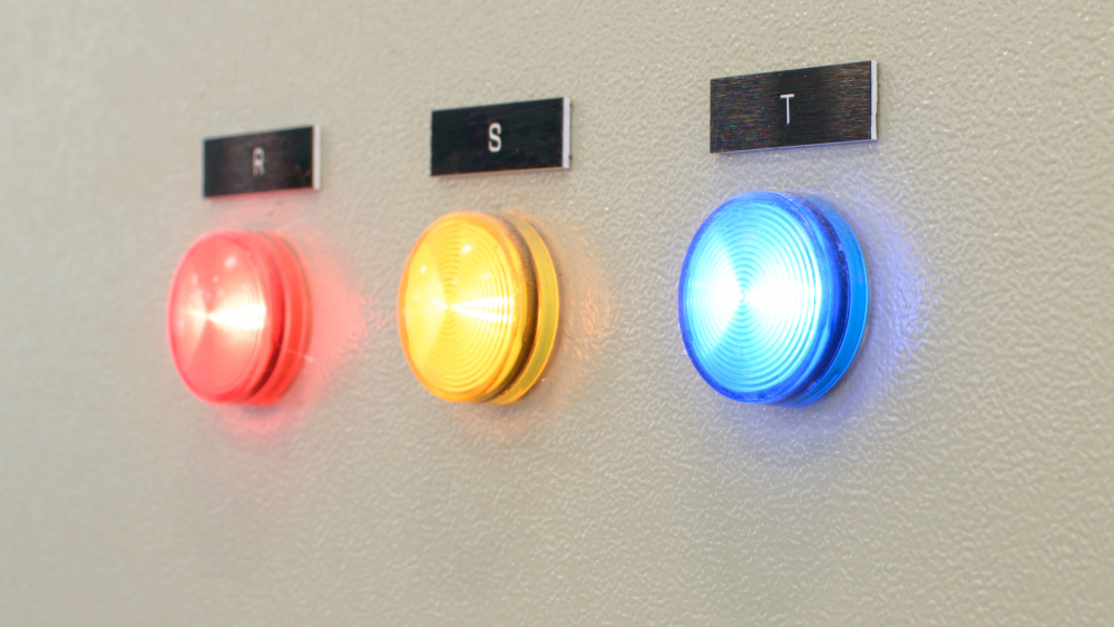
In some systems, the same status may need to be displayed in multiple locations on the panel face, or shown both on the panel face and a remote control panel, leading to multiple pilot lamps being connected in parallel to the same output.
Although each LED pilot lamp typically draws little current, combining several lamps can push the total current close to or over the rating of the PLC output, relay, or operating device. Verification must therefore sum the current of all lamps and check load limitations in the manufacturer documentation. If inrush current data or specific requirements for LED loads are available, they should also be factored into calculations.
Adding an interposing relay may be suitable in some cases, but it should not be considered a universal fix for every circuit, as coil ratings, output type, contact life, and reverse-voltage protection devices must also be considered. If selected improperly, the relay itself can become an improperly functioning load.
LEDs may glow dimly even when the output is turned off.
LED pilot lamps require very little current to illuminate, so you may find the lamp still glowing dimly or flickering even when the output is in an Off state. Causes may stem from solid-state output leakage current, snubber circuits, surge protection devices, or coupling from long parallel cable runs.
This symptom does not always mean the pilot lamp is defective, and it should not be resolved by adding a resistor or dummy load without proper calculation, as resistors can generate heat and place additional load on the circuit.
Begin by inspecting the output type, off-state leakage current rating, wiring routing, and connected protection circuits, then choose a solution based on recommendations from the relevant equipment manufacturer. If that lamp indicates a critical status, dim glowing can mislead operators, so it should not be left unexamined.
Keep control wiring as far from noise sources as possible.
Pilot lamp wiring is generally part of the control circuit group, especially in 24 VDC systems. If routed together with motor cables, power cables, or inverter output cables over long distances, it can be affected by induction or inter-cable coupling.
Inside the panel, control and power wire ducts should be properly separated. Avoid coiling excess wire near contactors, transformers, inverters, or high-power switching devices, and route grounding and shielding lines according to system specifications.
However, when a lamp flickers or glows dimly, do not immediately conclude it is solely inverter noise, as loose connections, unstable power supplies, output leakage current, or suppression circuits can cause similar symptoms.
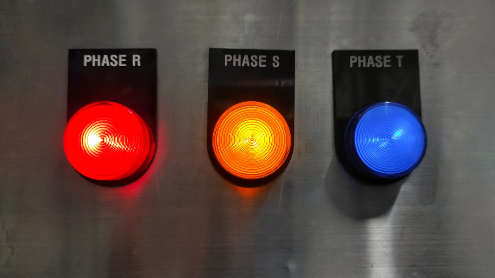
Group and position them for instant user comprehension.
A panel face with multiple pilot lamps should not be arranged merely by available empty space, but organized logically by operational sequence and status relationships, such as power supply group, operating mode group, motor status group, and fault or alarm group.
If it is a multi-pump control panel, you might align the Power, Run, and Trip lights for each pump in the same line or divide them clearly into separate sections for each machine. This helps reduce the chance of users misinterpreting the Run light of one unit as belonging to another.
Label positions should follow a consistent format throughout, such as placing the label below every lamp, rather than alternating some above and some below, because reading becomes difficult with a large number of lights. In addition, you should inspect from the actual position where the user stands, rather than looking only at the layout on a screen.
The rear of the panel door must also have enough clearance for the pilot lamp bodies, light modules, terminals, and wiring. If installed too close together, it may be inconvenient to tighten terminals, wires may crowd each other, or subsequent removal and replacement of components may become difficult.
Check mounting hole size, seals, and IP rating to suit the job site
Each pilot lamp model may require a different mounting hole size, such as 16, 22, or 30 mm, even among models with similar appearances. Before drilling the panel front, verify dimensions from the manufacturer's documentation; do not gauge visually from samples or rely on familiar dimensions without checking the actual model.
After drilling, deburr the edges and apply rust protection around the hole, especially on painted steel enclosures. If there are gaskets, seals, or rubber O-rings, ensure they are fully installed in the correct positions. Because pilot lamps pierce through the panel door, poor sealing can allow dust, water, or chemical mists to penetrate inside.
The IP rating specified by the manufacturer may apply only to the front of the device when properly assembled; it does not necessarily mean the rear or terminals have the same level of protection. Therefore, read the accompanying details and select equipment suitable for the area—such as indoors, washdown zones, dusty environments, or outdoor locations.
Indicator circuits must be properly protected
Although pilot lamps consume low current, the circuit wires and devices still require protection from abnormal currents. The selection of fuses, circuit breakers, or circuit grouping should correspond to the wire size, power supply capacity, and potential short-circuit current.
This does not mean every pilot lamp must always have its own individual fuse. Some systems may use group protection, while certain critical statuses might be isolated on separate circuits so a single point of failure does not shut off all lights simultaneously. The appropriate scheme must be determined from the panel design, not solely by the number of lamps.
Another point to watch is the power supply source. If a Power light is wired downstream of a circuit-disconnecting device, that light will turn off when the device is opened, but the incoming side of the device may still be energized. Users should never treat a turned-off pilot lamp as proof that the panel is de-energized.
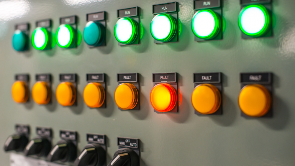
A light being off does not mean the circuit is de-energized
A pilot lamp can go out for several reasons, such as a failed LED module, a broken wire, a blown indicator circuit fuse, or a loose terminal, even while other areas inside the panel remain energized.
Before opening the enclosure, performing maintenance, or touching any part of the circuit, isolate power sources according to proper procedures, verify the absence of voltage with suitable test instruments, and control against accidental re-energization. Pilot lamps are intended to indicate status, not to serve as devices for proving zero energy.
Wire numbers and schematics must match the actual installation
When a panel has many pilot lamps, a large number of wires often share similar voltages and sizes. Without wire markers or device designations, future circuit tracing becomes difficult, and the chance of wiring errors increases significantly.
Each pilot lamp should have a designation such as H1, H2 or PL1, PL2 according to the organization's documentation standards, along with status descriptions, terminal numbers, and signal input points indicated in the schematic. After installation or modifications, update the As-built drawings to reflect the actual setup. Never leave discrepancies between the panel face, electrical drawings, and internal wiring.
Terminals must accommodate the quantity and type of wires inserted. Do not cram multiple wires into terminals not designed for them. Choose ferrules or wire lugs matching the wire cross-section, and tighten terminals to the specified torque to prevent loose connections, heat buildup, and intermittent breaks while opening and closing the panel door.
Test every status before commissioning
After installation is complete, do not just check that all lights illuminate; you must verify that they turn on and off under the correct conditions by simulating each operating state according to the circuit diagram.
You should check at least that the Power light illuminates from the specified power source, whether the Manual light turns off when Auto mode is selected, and whether the lights indicating Run Command, Contactor On, or Running Feedback display according to their intended meaning when commanding the machine to operate, including testing Trip and Fault conditions in a safe manner.
Undesirable simultaneous conditions should also be checked, such as two modes illuminating at the same time, LEDs faintly glowing when an output is turned off, or Fault indicator lights extinguishing when a portion of the control circuit loses power even though the operator should still receive an alert.
For enclosures with complex systems, a Cause and Effect matrix may be prepared to specify which light should turn on, which light should turn off, and which device should respond when an event occurs. This approach facilitates a more systematic inspection during handover and future circuit troubleshooting.
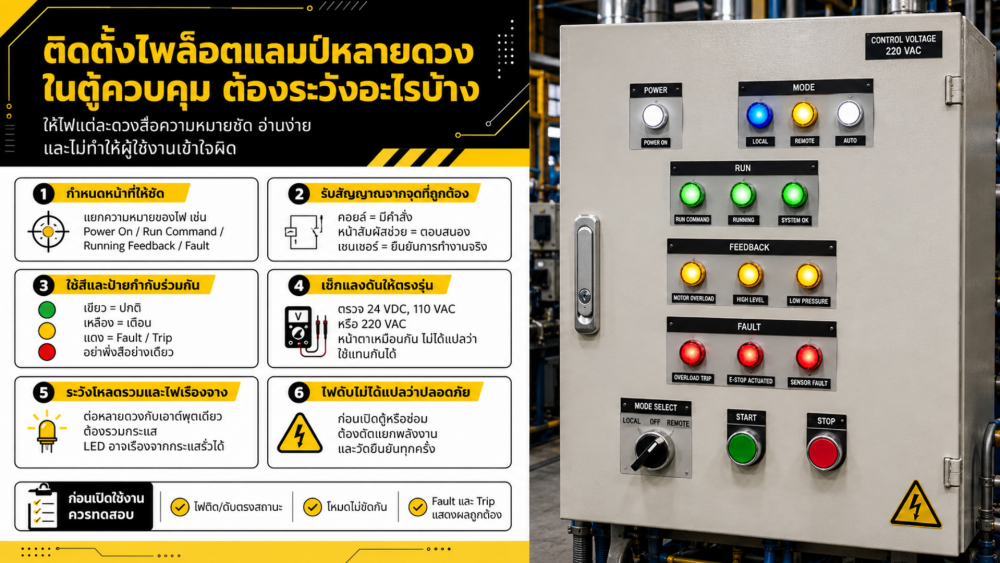
The number of lights is not as important as the information the operator receives.
A control panel withPilot Lightsa large number does not necessarily mean it is easy to use. If some lights display redundant information, use inconsistent color schemes, or illuminate from points that do not reflect the actual state of the machine, users may waste time troubleshooting circuits and may make incorrect decisions based on the observed status.
Good installation should provide each light with a clear function, use the correct voltage rating, receive signals from appropriate locations, and be arranged for easy reading. When combined with proper labeling, circuit schematics, and comprehensive testing, pilot lights help operators look at the panel and understand what state the machine is currently in and which section to check next without causing confusion for users or maintenance technicians.