


 EN
 ไทย


Customers Also Purchased


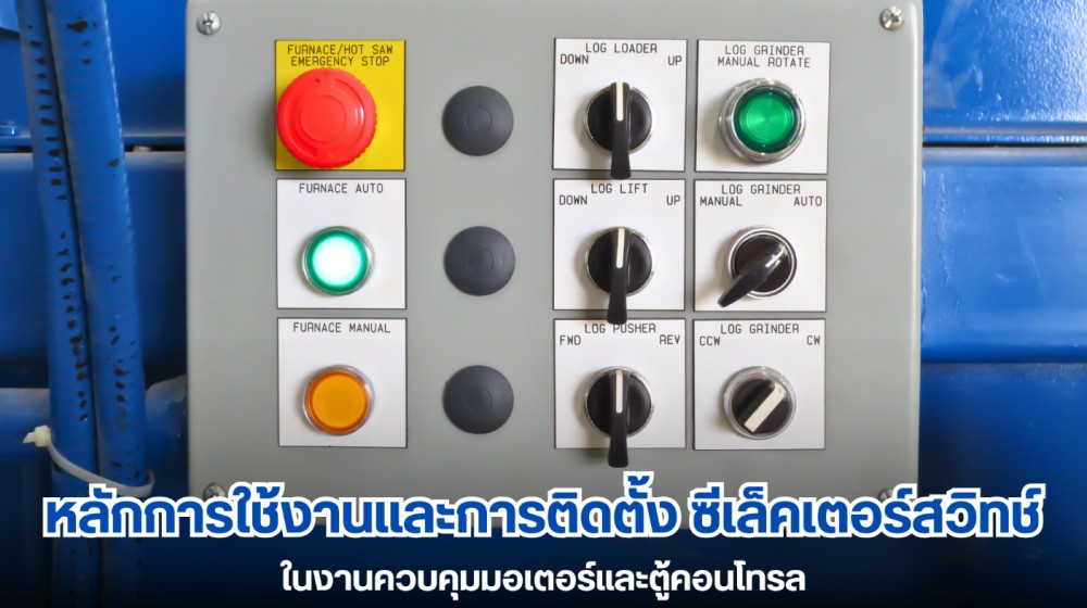
A Selector Switch is a rotary control switch widely used in electrical systems, motor control, and various control panels. Its key advantage is the ability to "select multiple operating modes" via a single switch, such as Auto / Manual, Forward / Reverse, or selecting between multiple sets of loads. This ensures sequential control, prevents conflicting commands, and enhances operational safety.
A selector switch does more than simply turn a circuit on or off; it functions as part of the control logic that relies on multiple contact blocks to properly switch system operating states. In this article, our technician will dive into the most common application scenarios, along with circuit diagrams and installation guidelines, so readers can apply them practically and safely to motor control and control panel projects.
The Crucial Role of Selector Switches in Electrical Control Applications
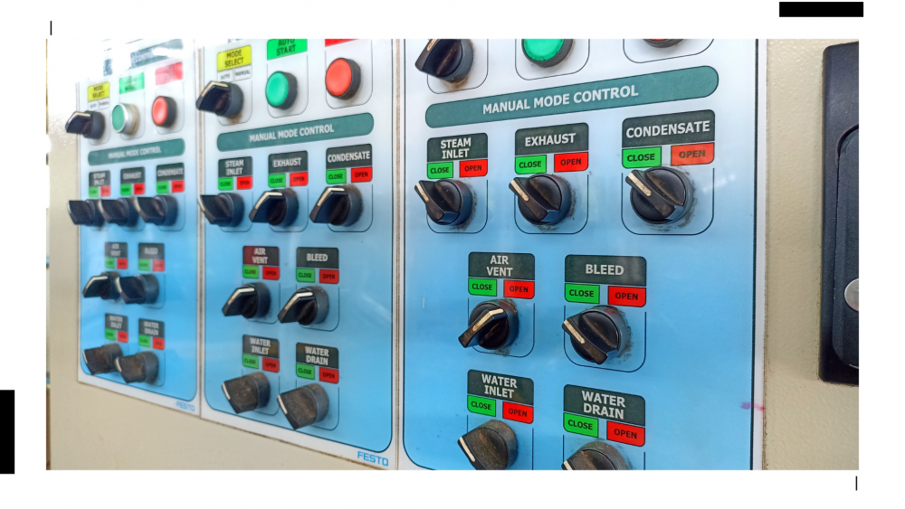
In electrical and machinery control systems—whether small control enclosures or large industrial setups—one component found in almost every panel is the selector switch. Because this device can "select multiple operating states in a single unit," it helps operators control operational sequences more clearly without the complication of using multiple pushbuttons for the same task. Selector switches are therefore ideal for applications requiring mode switching or specific sequential commands, such as:
- Selecting water pump modes: Auto / Off / Manual
- Setting motor rotation direction: Forward / Reverse
- Selecting active loads, such as lighting group 1 or group 2
- Switching fan speed levels in ventilation systems
- Selecting control sources between Local / Remote
Crucially, when the operator turns the switch to a specific position, the NO/NC contacts on the back immediately change state according to that mode. This ensures commands execute in the designed sequence, minimizes overlapping signals, and helps prevent errors typically caused by multiple pushbuttons being pressed simultaneously by accident. Furthermore, using a selector switch reduces the number of components on the panel door, keeping the control panel tidy and easier to inspect—especially in applications demanding clear operating modes and safe circuit switching.
How Does a Selector Switch Work?
Although a selector switch may look like a simple rotary switch from the outside, its internal design is actually intricate, allowing it to handle multiple commands simultaneously in a single device—including mode switching, circuit alternation, and sequential command control in various control applications. The internal structure of a selector switch works together in key steps as follows:
1. Actuation via Rotary Position
The rotary position of the selector switch is the heart of its operation, because "each position" acts as a predefined "circuit state", such as:
- Position 0 = Turn off all circuits
- Position 1 = Turn on circuit 1
- Position 2 = Turn on circuit 2
With just a single turn of the switch by the user, multiple sets of connected circuits can be commanded to operate simultaneously, such as:
- Activating the Auto circuit
- Disconnecting the Manual circuit
- Sending a status signal to the PLC so the system knows which mode it is in
- Turning on the indicator light on the front panel
Commanding multiple conditions simultaneously like this makes the selector switch extremely useful in applications requiring strict command sequencing, such as motor systems, pumps, and automated systems that must prevent incorrect mode commands.
2. Internal Cam System
The mechanism that allows a selector switch to precisely change contact states is the internal "cam". The cam rotates along with the switch position turned by the user and serves to press or release the contacts of each contact block, opening or closing them according to the designed sequence.
Highlights of the Cam system include:
- Precise rotary position control
- Reduces the deviation of getting stuck between positions
- Ensures each position stops firmly with a distinct click
Because of this, selector switches are highly reliable for applications requiring 100% accurate operation, such as switching motor modes or commanding rotation direction, which heavily depend on positional precision.
3. NO/NC contacts change states according to the operating mode
The rear of a selector switch features NO (Normally Open) and NC (Normally Closed) contact blocks that switch states when the user turns the knob to different positions. A single mode may require multiple contacts to operate together, for example:
- Mode Auto Must close the Auto NO contact while opening the Manual NC contact
- Mode Forward Must close the FWD NO contact while opening the REV NC contact to prevent conflicting directions
- Mode Manual Must disconnect the Auto signal first to prevent the automatic system from sending conflicting commands
These contact blocks are the mechanism that allows the selector switch to function completely as a basic "Control Logic" device inside a control panel without relying on additional electronic devices in many cases.
Practical Applications of Selector Switches
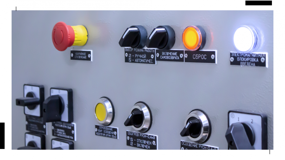
Most electrical control tasks in factories rely on selector switches to select operating modes and control command sequences. The examples below are the most common applications, accompanied by text diagrams to clearly illustrate how they work.
1. Controlling Motor Auto / Manual Mode
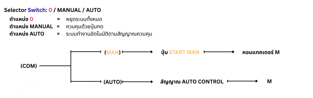
Auto/Manual mode selection is one of the most common applications for selector switches in water pump systems, machinery, and general automation systems. The importance lies in defining whether "the system runs automatically or under manual user control".
 Operation Explanation
– User switches to Manual → Uses pushbuttons to control the machine manually
– Switch to Auto → System operates according to sensors, timers, or a PLC
– Position 0 → Cuts off all commands
Pros: Safe, correct command sequence
Cautions: Manual and Auto must not be engaged simultaneously
2. Controlling Motor Forward/Reverse Rotation Direction
Many motor control tasks require commanding rotation in Forward or Reverse directions. A 3-position selector switch is ideal for this, as it allows safe direction selection and minimizes the chance of simultaneous conflicting commands.
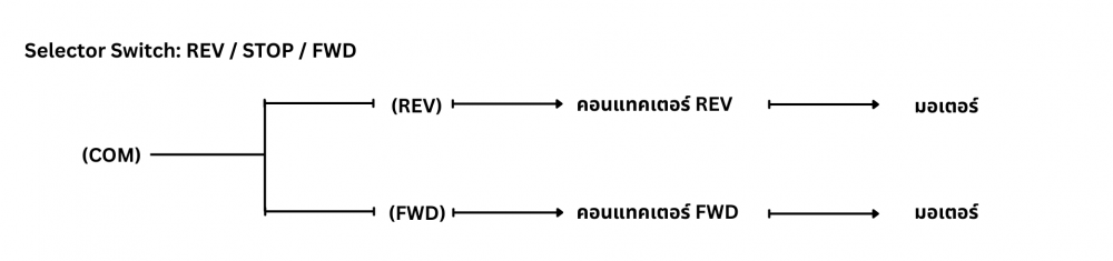 Operation Description
- Turn to FWD → Motor rotates forward
- Turn to REV → Motor rotates in reverse
- Position STOP will disconnect all circuits before changing direction to prevent power surges and motor damage
Mandatory conditions (crucial)
- NC of REV must disconnect FWD
- NC of FWD must disconnect REV
This is called Interlock to prevent operating in both directions simultaneously, which causes short circuits and motor damage in real-world applications
3. Selecting a load or circuit to operate one set at a time
This is a common application found in general systems such as lighting systems, fan systems, or systems with multiple devices where only one device needs to operate at a time to control the load or alternate usage.
Examples of selectable equipment include:
- Lighting Group 1 / Group 2
- Fan 1 / Fan 2
- Water Pump A / Water Pump B
 Advantages of this type of application
- No need to install multiple switches
- Users can clearly see which load is currently selected
- Reduces complex wiring
- Suitable for systems requiring sequential management of multiple loads
4. Control Source Selection – Local / Remote
Many machine applications require choosing whether control is executed from the local machine panel (Local) or via a PLC / HMI system (Remote). Selector switches are the most suitable choice for switching control sources without allowing simultaneous conflicting commands.
 Benefits of a Local / Remote System
- Reduces confusion during machine maintenance or adjustment
- Technicians can control the system directly at the machine without going through the PLC
- Minimizes the risk of conflicting command signals arriving simultaneously from two sources
How to Properly Install a Selector Switch
Installing a selector switch requires precision, as the rotary position and contact engagement directly affect system operation. Even a minor installation error can cause the circuit to operate in the wrong mode or fail completely. Below is a simplified, practical installation guide summarized by Nong Chang for control panels.
4.1 Mounting Hole Sizes
Common selector switches are available in two main sizes used in practical applications, including:
- 22 mm – The most common standard size, suitable for general control panels
- 30 mm – Used in heavy-duty industrial applications or where greater durability is required
Drilling the panel cutout should be done with a standard-sized hole saw or punch so the switch fits snugly into place—neither too tight to deform the switch body, nor too loose to cause rotation misalignment.
4.2 Proper Installation Steps
To ensure that the selector switch functions perfectly and maintains precise rotary positioning, Nong Chang recommends following these installation steps:
1. Determine the mounting position on the panel: Measure accurately and maintain an adequate distance from other devices so that the operator can rotate the switch comfortably.
2. Drill the hole using a drill bit matching the 22 or 30 mm size: Using an incorrectly sized drill bit may cause the switch body to twist or fail to lock into place properly.
3. Insert the switch from the front of the panel: Ensure the switch body fits properly into the hole, without being tilted or misaligned.
4. Tighten the rear locking ring appropriately: It must be tight, but do not overtighten it as it may deform the switch body or make it stiff to turn.
5. Install the contact blocks (NO / NC): According to the circuit diagram to be used; some systems only require 1–2 contacts, but motor systems or Auto/Manual setups may require multiple contact blocks.
6. Wire from the COM and function lines to the control circuit: Route the wiring neatly to prevent confusion between contact positions.
7. Test the switch operation in each position: Use a multimeter to check the NO/NC states to ensure they function according to the circuit design.
8. Clearly label the operating modes: Such as AUTO / MANUAL / OFF; this is a small detail but very important, as it helps prevent turning to the wrong mode during actual operation.
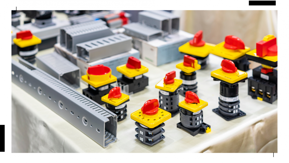
4.3 Common Installation Mistakes
Although selector switches are easy to install, the following errors are commonly found in practice and can cause incorrect commands or unstable system operation:
- Installing contacts in the wrong position (swapping NO/NC): Causes incorrect mode commands, such as Auto engaging simultaneously with Manual, or Forward not cutting out Reverse.
- Installing the switch tilted or misaligned: Results in the knob position not aligning with the scale markings and causes confusion for users
- Not turning the switch fully into position: Prevents contacts from closing properly and disrupts continuous circuit operation; sometimes causing erratic motor operation
- Not testing contacts before actually powering up the system: Checking with a multimeter is a step often overlooked, but it is essential to confirm that contacts operate correctly
- Using insufficient contacts for the required functions: Such as in Auto/Manual systems that require multiple separate contact sets, but only one set is used, causing circuit conflicts
These mistakes often happen during initial installations. A thorough check before actual operation will greatly help prevent subsequent issues.
Guidelines for choosing the right selector switch for your application
Selecting the right selector switch from the start will ensure your control circuit operates safely, reduces errors, and makes installation much easier. The selection principles summarized below can be applied to motor controls, machinery, and general control applications.
1. Determine the number of required positions (2 or 3 positions)
The number of positions on a selector switch must match the system's function, for example:
- 2 Positions (0–1) → Used for On–Off or selecting A/B
- 3 Positions (0–1–2) → Used for Auto/Off/Manual or Forward/Stop/Reverse
Choosing the appropriate number of positions for the job ensures clear operation and reduces user confusion
2. Determine the required number of NO/NC contacts based on functionality
Each mode requires a different number of contacts, for example:
- Auto/Manual → Requires separate contacts for Auto and Manual
- Forward/Reverse → Requires contacts for interlocking for safety
Choosing insufficient contacts may cause the circuit to execute commands out of sequence or result in overlapping commands. Therefore, you should check the circuit in advance to see how many NO and NC points are required.
3. Choose between maintained or momentary types (Maintained / Momentary)
Selector switches are available in 2 main operational types:
- Maintained type → Stays in the turned position, such as Auto, Manual, Forward
- Momentary type (spring return) → Springs back after being turned, such as Reset, Jog
Choose the type according to its function, because using the wrong switch type can cause incorrect circuit timing; for example, using a momentary type for Manual mode will prevent the system from holding the command as needed.
4. Choose an operator head suited for the application (Knob / Lever / Key)
Selector switch operator heads come in various styles, such as:
- Knob (Standard rotary knob) → For general use, easy to turn
- Lever (Long handle / lever) → For applications requiring frequent mode changes
- Key Selector (Key-operated type) → Ideal for applications where user access needs to be restricted
Selecting the right operator head helps reduce errors from turning to the wrong position and enhances system safety.
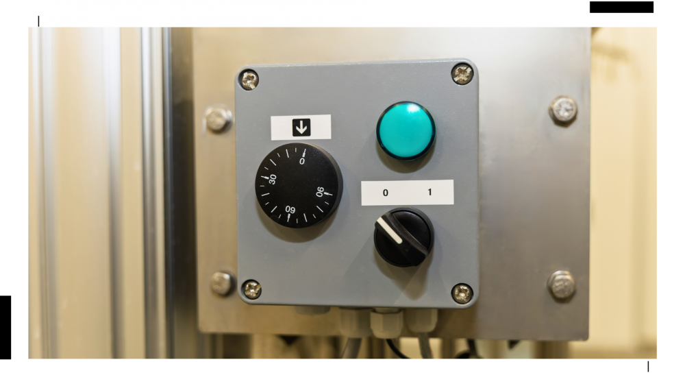
5. Check brand standards and durability
Should choose Selector Switches from brands that meet industrial standards, such as having proper current ratings, heat resistance, and complying with safety standards like IEC, especially for motors or machinery requiring continuous operation.
Brands commonly found on the market include Schneider, ABB, IDEC, Fuji, etc., each offering a wide selection of accessories and contact blocks.
5.6 Use models with clearly marked legend plates
Position indicator plates such as
- Auto / Off / Manual
- Fwd / Stop / Rev
- Local / Remote
are small items that are extremely important because they help prevent turning the switch to the wrong position. Especially in areas with multiple operators, having clear labels greatly enhances system safety.