


 EN
 ไทย


Customers Also Purchased
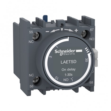
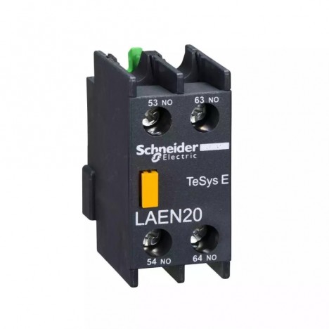
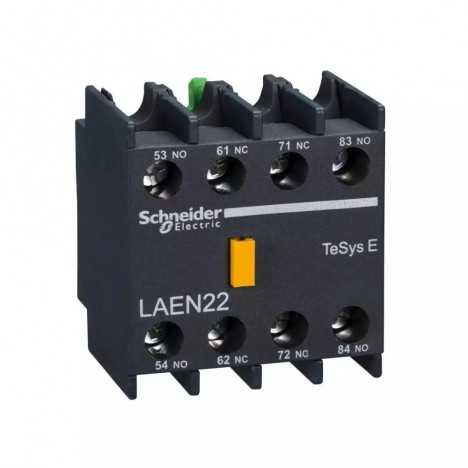
In industrial electrical systems, devices responsible for safely and accurately switching high-power loads on and off are vital—especially in applications involving motors, pumps, heaters, or machinery running continuously for long periods. "Magnetic Contactor" It has therefore become a staple component found in virtually every control cabinet, engineered to withstand high inrush currents, handle countless switching cycles, and integrate smoothly with automated control systems.
To provide a clearer picture, in this article Nong Chang will introduce you to the structure, operating principles, and reasons why nearly every industry relies on magnetic contactors.
What is a Magnetic Contactor?
A magnetic contactor is an electrical device used to switch high-power loads "on and off" by receiving commands through a lower-voltage control coil, such as 24V, 110V, or 220V. When voltage is applied to the coil, it generates a magnetic force that pulls the main contacts closed, safely delivering actual power to motors, pumps, or heaters. Turning off the circuit is very simple: just cut off power to the coil, and the contacts will release, instantly stopping the power supply to the load.
What sets a contactor apart from standard relays is its heavy-duty capability—whether handling inrush currents during motor startups, accumulated heat from continuous operation, or frequent switching cycles. Contactors are specifically engineered to endure these conditions.
From Nong Chang's perspective, the greatest highlight is "stability." No matter how frequently it is operated, a high-quality contactor consistently performs its duty: receiving a low-power signal from the coil and accurately delivering high power to the load without the risk of arcing or the need for bulky manual switches, all while integrating seamlessly with modern control systems like PLCs.
For all these reasons, magnetic contactors are considered a vital component in factory electrical control systems—truly indispensable.

Structure and Functions of Main Components
Even though contactors from almost every brand look similar on the outside, it is the internal components that make all the difference in quality. Some models are durable and long-lasting, while others fail quickly. It all comes down to materials, assembly quality, and internal design, as each individual part directly affects stability, heat dissipation, service life, and overall electrical system safety.
Coil
This part receives control voltage to generate a magnetic field. A properly designed coil must withstand voltage drops and heat; otherwise, it may fail to pull in completely, preventing the main contacts from closing tightly and easily leading to accumulated heat. Nong Chang considers the coil a small yet crucial part—if the coil is unstable, the entire system becomes unstable.
Armature / Plunger
This is the moving part pulled by magnetic force to open and close contacts precisely. It is a clear indicator of a contactor's quality: a poor design causes humming, vibration, or incomplete closure, which inevitably reduces service life.
Main Contacts
This is where the entire load current flows, meaning it must be made of high-grade materials with high arc resistance. Subpar contacts will develop burn marks or pitting under heavy loads or frequent switching, leading to incomplete contact and rapid heat buildup. That is why choosing the right brand and specification requires meticulous attention.
Auxiliary Contacts
Used to control circuits such as self-holding, interlocking, sending feedback signals to a PLC, or indicating status. Although they do not handle heavy loads, they allow the entire control system to operate sequentially and much more "intelligently."
Arc Chute
Designed to contain and extinguish electrical arcs when contacts open, protecting them from damage and reducing heat buildup inside the control cabinet. High-quality contactors feature multi-layered arc chutes made of specialized flame-retardant materials, significantly extending their service life.
Operating Principle of Magnetic Contactors
In the simplest terms from Nong Chang: "The coil uses low power to control, while the main contacts use high power to drive the actual load."
The internal operation sequence is as follows:
1. Coil receives voltage: A magnetic field is created instantly within milliseconds.
2. Iron cores are pulled together: A "click" sound occurs, signaling that the mechanism has engaged.
3. Main contacts close the circuit: The load receives power, such as a motor starting to spin or a heater beginning to operate.
4. Auxiliary contacts change state: Used in control circuits, such as self-holding or interlocking circuits.
5. When power to the coil is cut, the circuit stops immediately: The spring pushes the iron core back, the contacts open, and the circuit is cut safely.
When putting all steps together, you can clearly see that a contactor acts like an "assistant that receives small commands and manages heavy tasks for us." This ensures that high-power load control systems in factories remain stable, safe, and capable of handling frequent repetitive cycles without wearing out easily.

Load Types and Why Choosing the Right Contactor Type Matters
When talking about contactors, many people focus solely on the "ampere" rating, even though "load type" is just as important. Contactors are engineered to handle the differing behaviors of each type of load. The IEC standard defines these as AC-Classes, which immediately indicate the kind of application a contactor is suited for.
AC-1
Suitable for non-inductive loads such as heaters, ovens, or loads with steady current draw. This type of duty produces minimal arcing, causing slow contact wear and offering the longest service life of all categories.
AC-3
Suitable for general motors, whether water pumps, fans, or conveyors. Because motors generate very high inrush currents upon starting—sometimes 5 to 7 times the operating current—AC-3 contactors must significantly withstand greater inrush currents and contact wear compared to AC-1 types.
AC-4
For applications with highly frequent switching cycles, such as continuous stop-run-stop sequences. These loads create more severe arcing than usual, so the contactor used must feature exceptionally durable contacts, ideal for specialized jobs demanding maximum ruggedness.
Selecting the wrong contactor for your load type leads to premature contact wear, sometimes causing issues in just a few months because it wasn't designed to handle that specific load behavior in the first place. Therefore, choosing the correct AC-Class is crucial.
Why Factories Need Magnetic Contactors
Contactors aren't installed merely to "meet code standards"; they are truly essential in industrial systems because they solve multiple issues that other devices simply cannot.
Safely Control High-Power Loads
General switches are not designed to handle inrush currents or the high operating currents of motors. Controlling high-power loads always requires a contactor to ensure safe switching without heat buildup or sparks that could endanger the system.
Supports automation systems
PLCs, timers, or control relays issue commands only at the control level and cannot supply high-power electricity directly to loads. Having a contactor as an "intermediary" allows the control system to fully operate motors or machinery.
Used in conjunction with overload relays
Overload relays help protect motors from overcurrent conditions. When an anomaly occurs, the relay immediately cuts power to the coil, causing the contactor to release the load quickly and significantly reducing the risk of motor burnout.
Interlocking to prevent out-of-sequence operation
A clear example is the Star–Delta system, which requires multiple contactors to alternate operation. If poorly designed or if any unit operates out of sequence, it could blow fuses or damage the motor. Therefore, contactors must be used with interlocking for maximum safety.
Longer service life and more durable than general relays
Contactors from standard-compliant manufacturers are typically designed for "hundreds of thousands to millions" of switching cycles, easily handling heavy-duty use in factories.

Signs that a contactor is failing
In industrial systems, contactors often cycle tens of thousands of times per month. Observing abnormal symptoms greatly helps reduce the risk of unnecessary machine downtime.
1. Humming sound from the coil
Usually caused by unstable coil voltage or a deteriorated shading coil, making the iron core vibrate during operation. Leaving it unchecked increases the risk of overheating contacts.
2. Blackened, burnt, or pitted contacts
Indicates that arcing occurs frequently and with increasing severity. This wear impedes full current flow, resulting in inconsistent system operation and causing the motor to heat up more easily.
3. Incomplete pull-in or chattering
May be caused by coil voltage drop, instability, or internal mechanical obstruction. This symptom should be inspected immediately to prevent heat buildup at the contacts.
4. Hot coil or unusual odor
When the coil runs hotter than normal, it may indicate overloading, incorrect supply voltage, or coil degradation. Replacing it before overheating becomes excessive is the safest choice.
Conclusion
Magnetic Contactors It may be just a small component in the control panel, but its role is much bigger than it appears. It acts as the intermediary that allows the system to operate high-power loads safely, easily, and seamlessly alongside automation systems. Whether it's motors, pumps, or heaters, everything relies on contactors for precise switching.
Once you understand the structure, working principles, load types that must be correctly selected, and warning signs of impending failure, designing, installing, and maintaining industrial electrical systems will become much more efficient. Nong Chang views contactors as one of those "small but essential" components—if chosen properly, the entire system will be both stable and safe.