


 EN
 ไทย



Customers Also Purchased
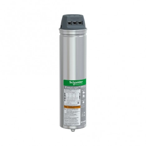
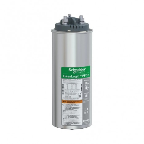
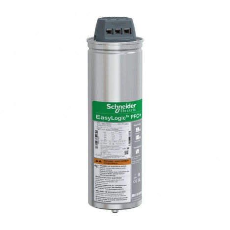
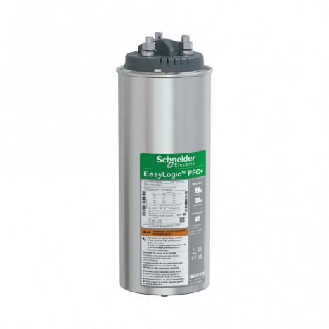
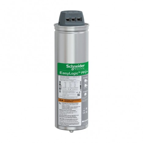
In alternating current (AC) electrical systems of factories and large buildings, the "Power Factor (PF)" is a crucial metric that directly affects energy efficiency, transformer load capacity, and electricity costs. One of the standard engineering devices used to improve PF is the PFC capacitor. Capacitors (Power Factor Correction Capacitor)
This article brings together comprehensive knowledge across every dimension—from fundamental principles, differences from general capacitors, and kVAR sizing calculations, to selection in harmonic-rich systems, and installation and maintenance guidelines in accordance with international standards.
What Is Power Factor and Why Is It Important?
In an AC electrical system, electrical power is divided into 3 main components:
- Real Power (kW): The power actually used to perform work, such as rotating a motor shaft, providing heat, or producing light
- Reactive Power (kVAR): The power necessary to establish magnetic/electric fields, but which does not produce net work
- Apparent Power (kVA): The total apparent power (the vector sum of kW and kVAR)
Basic relationship:
PF = kW / kVA = cosθ
When the PF is low (e.g., 0.7–0.8):
- Total current (I) is higher for the same amount of real power
- Conductor losses increase (I²R losses)
- Transformers and switchgear handle greater loads
- Power utility penalties may be incurred (if lower than the mandated threshold)
Engineering objective In factories, the target PF is typically set around 0.95 or higher (while avoiding overcompensation that leads to a leading PF).
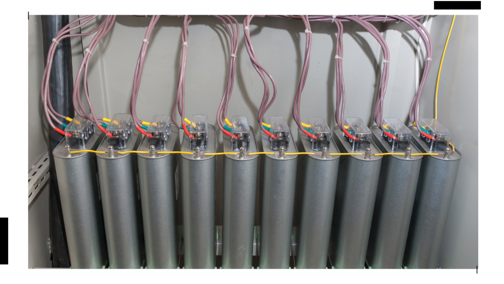
How Reactive Power Occurs in Factories
Most loads in factories are Inductive loads (Inductive Load) Such as:
- 3-phase induction motor
- Transformers
- Welding machines
- Compressors
These devices require energy to create a magnetic field, resulting in Inductive reactive power (Inductive kVAR) causing the current to lag the voltage (Lagging PF)
The correct solution is to supply Capacitive reactive power (Capacitive kVAR) to compensate at the point of use, reducing the flow of kVAR from the main power source. This is the function of a PFC capacitor.
What is a General Purpose Capacitor?
General purpose capacitors are widely used in general electronics and electrical applications, such as:
- Ripple filtering in power supply units (Electrolytic)
- Signal coupling/bypassing (Ceramic/Film)
- Time delay in circuits
- Starting small motors (Motor Start/Run)
Key characteristics:
- Capacitance specified in µF, nF, pF
- Not designed to withstand continuous high RMS currents in power systems
- Not rated in kVAR for system-level reactive power compensation
Conclusion: General purpose capacitors are not suitable for power factor correction in industrial electrical systems.
What is a PFC capacitor and how does it work?
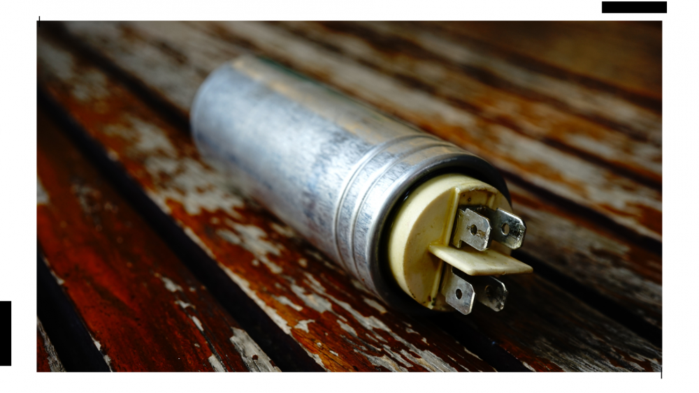
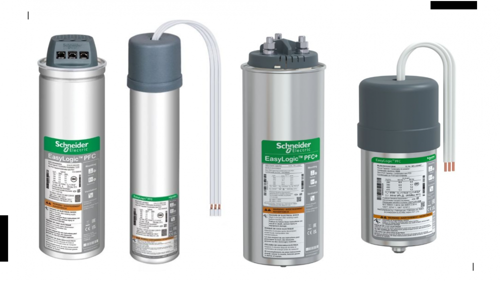
PFC capacitor is a capacitor for power systems installed in shunt with the system to supply Capacitive Reactive Power compensate for inductive loads
Typical technical specifications:
- Operating voltage 400V, 415V, 440V (low voltage system)
- Power rating specified in kVAR
- Supports high RMS current and switching inrush current
- Construction is typically Metallized Polypropylene (Self-healing)
- Designed according to standards such as IEC 60831
Operating principle:
- When connected to the system, the capacitor generates a leading current
- The leading current cancels out the lagging current from inductive loads
- Reduces kVAR drawn from the power source → reduces total kVA → increases PF
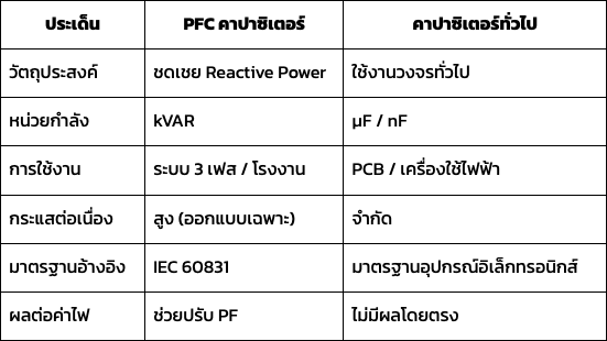
Technical differences: PFC vs. standard capacitors
Why improving PF helps reduce electricity bills
- Reduces total system current: For the same kW, if PF is higher, kVA decreases, reducing current → reduces I²R losses
- Increases transformer load capacity: When kVA decreases, the transformer can handle more real operating load
- Reduce the chance of low PF penalties: Electricity service providers in many areas set minimum PF standards.
- Improved voltage stability in some cases: Current reduction helps decrease voltage drops along the cables.
Note: Compensation must be appropriate, without excessive levels leading to Overcompensation.

Types of PFC Capacitors and Capacitor Banks
Selecting the type of PFC capacitor does not depend only on the kVAR rating, but also on the "electrical system load characteristics", as each system exhibits different energy usage patterns.
Generally in industrial applications, they are divided into 3 main types as follows:
1. Fixed Capacitor
Operating characteristics: A capacitor permanently connected to the system (connected continuously at all times) to supply a constant Reactive Power.
Suitable for:
- Loads that remain relatively constant throughout the day
- Large motors operating continuously
- Systems without significant load fluctuations
Pros
- Simple structure
- Low installation cost
- Easy maintenance
Cautions: If the load drops significantly while the capacitor continues to deliver the same kVAR, the following may occur:
- Leading Power Factor (Leading PF)
- System overvoltage
- Instability during certain periods
Therefore, Fixed Capacitors are suitable only for systems with "stable load behavior".
2. Automatic Capacitor Bank (APFC)
Operating characteristics: This is a capacitor bank divided into multiple steps (e.g., 10, 20, 30 kVAR) that uses a Power Factor Controller to monitor the PF in real-time, then switches each step on or off to suit the load at that moment.
Suitable for:
- Factories with loads fluctuating throughout the day
- Systems with frequently switched on/off motors
- Office buildings or shopping malls where loads vary by time of day
Pros
- Precise PF control (e.g., target 0.95)
- Reduces the risk of overcompensation
- Adapts to the actual load
Key engineering points
- Must select an appropriate number of steps
- Step sizes should not differ too drastically
- Should be calculated to provide sufficient resolution for control
APFC is considered the standard in modern factories because it addresses constantly fluctuating loads.
3. Detuned Capacitor Bank (with Reactor)
In systems with power electronic equipment, such as:
- Variable Speed Drive (VSD)
- UPS
- Rectifier
- Inverter welding machines
will occur Harmonics which are currents at frequencies higher than the fundamental 50 Hz frequency
If standard capacitors are installed in a system with high harmonics, the following may occur:
- Capacitor current exceeding rated capacity
- Heat accumulation
- Resonance with system impedance
- Premature failure
Working Principle of a Detuned System
will be connected Reactor (L) in series with the capacitor (C) to:
- Tune the resonance frequency of the LC circuit
- Shift the resonance point below the dominant harmonics (e.g., 189 Hz for a 50 Hz system)
- Reduce harmonic amplification
Suitable for:
- Factories with many VSDs
- Systems with high THD
- Industry 4.0 factories
A Detuned Capacitor Bank is therefore not a "premium option", but in many cases an "engineering necessity"
Accurately Calculating kVAR Rating
Must know:
- Active Power (kW)
- Original PF (PF1)
- Target PF (PF2)
Standard formula:
kVAR = kW (tanθ1 − tanθ2)
Where:
- θ1 = arccos(PF1)
- θ2 = arccos(PF2)
Example calculation:
- 500 kW load, original PF 0.80, target 0.95
- Calculate the tanθ value for each PF and substitute into the formula to find the required kVAR to install
It is recommended to allow a slight margin and divide into steps when using an APFC
Summary for decision makers
If you manage:
- Industrial factories
- A large office building
- A system with many motors
and find a low PF → using a PFC capacitor designed to standards is the sound engineering approach
- Standard capacitors are suitable for electronic applications
- PFC capacitors are suitable for power system applications
Choosing the right equipment not only reduces electricity costs, but also improves the long-term stability and safety of the electrical system